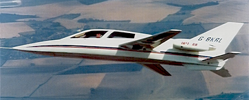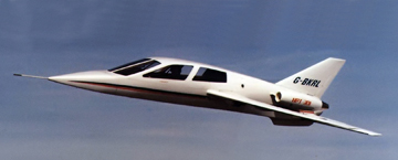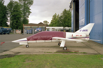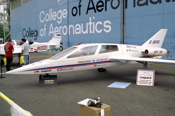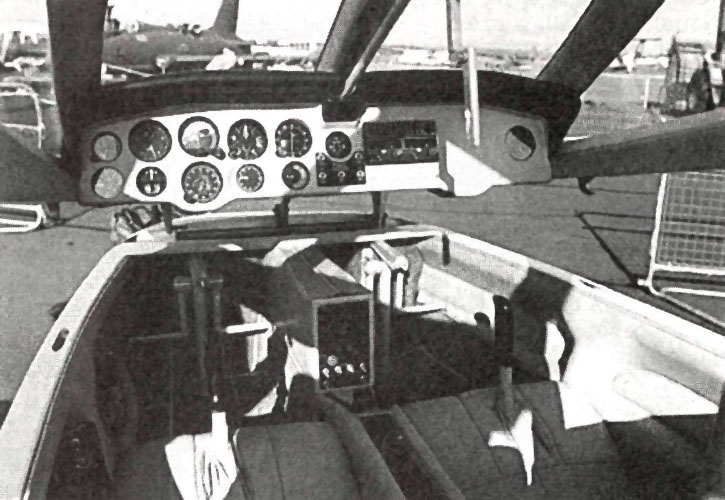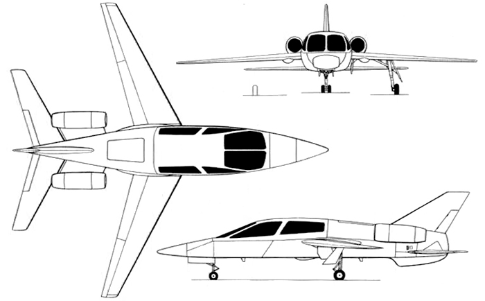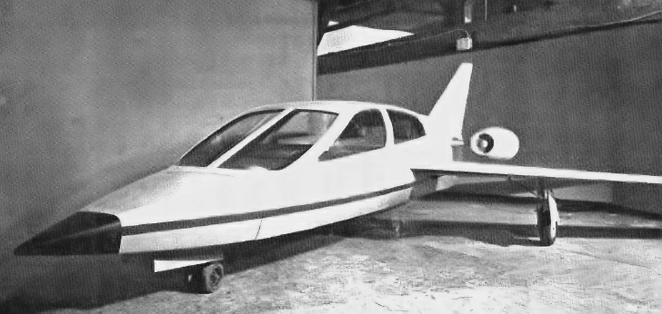
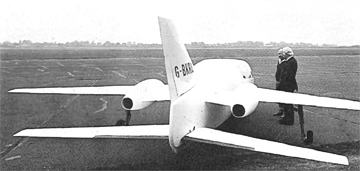
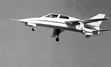
le CMC Leopard I est un jet d’affaires léger de haute performance conçu par M. Ian Chichester-Miles, ancien ingénieur en chef de la division Avions de British Aerospace à Hatfield (dans le Hertfordshire),via sa société Chichester-Miles Consultants (CMC).
Cette version de l’appareil, a volé en étant équipé de deux turboréacteurs Noel Penny NPT 301-3/4
La conception de ce « Personal jet » de quatre places a débuté en Janvier 1981. Elle était suffisamment avancée pour disposer d’une maquette début de 1982. La conception et la construction du prototype a été confiée à DesignAbility Ltd à Dilton Marsh, dans le Wiltshire. Le travail a débuté en juillet 1982, sous contrat avec CMC.
First Flight
The prototype flew for the first time in decembre 1988 at RAE Bedford, in the hands of Cranfield test pilot Angus McVitie.
CMC has limited the aircraft to 130kt and a maximum altitude of 3,500ft.
The Leopard prototype was tested from speeds as low as 75kt with maximum 41° flap.
Minimum zero-flap speed was less than 90kt.
Undercarriage cycling was proved during this flight.
Description of the CMC Leopard I
Type
Four-sea light business jet aircraft.
Wings
Cantiler mid-wing monoplane. ARA designed wing section and 3D profiles combining laminar flow and super critical wing technology.
Thickness/chord ratio 14% at root, 11% at tip.
Sweepback at quarter-chord 25°.
Two-spar structure, primarily of GFRP, with some carbonfibre reinforcement. Full span electrically actuated trailing-edge flaps of carbonfibre, with deflections of +/- 45° for high drag landing and air-braking/lift dumping. No ailerons or spoilers.
Production aircraft was planned with liquid de-icing and decontamination system in leading-edge.
Fuselage
Built in three sections : Unpressurised nose section accomodating avionics and nosewheel gear when retract, pressurised cabin section (production aircraft only) and unpressurised rear section providing a baggage bay, with fuel tanks below and equipment bays to rear.
Basic monocoque structure, primarily of GFRP with some carbonfibre reinforcement; fore and aft cabin bulkheads, engine and tailplane axle frames moulded in.
Pressure cabin section divided approximately along aircraft horizontal datum, with upper section formed by electrically actuated upward opening canopy hinged at windscreen leading-edge. Multiple latches around canopy lower-edge. Bonded-in acrylic side windows carry pressurisation tension. Nose opens for access to avionics.
