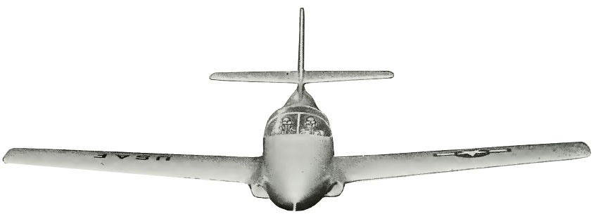
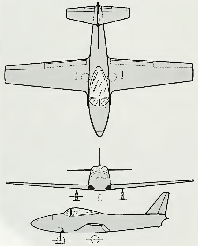
Projet Ryan Model 59
[svg-flag flag=”us” size=”1.1″ size_unit=em] The Ryan Aeronautical Company
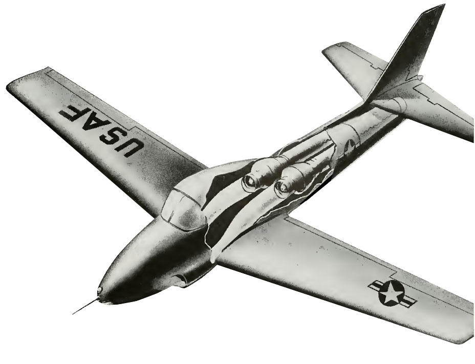
With the Projet Ryan Model 59 Primary Phase Trainer, Ryan wanted to offer an unusual opportunity to conduct a test program in a single airframe with both the Allison engine and the dual Marbore installation, as well as with any other power plants which can be provided.
Flexibility of design that permits interchange of power plants and versatility of function was the prime characteristic of Ryan Aeronautical Company’s Model 59 Primary Phase Jet Trainer whose unusual features had attracted widespread interest.
Entered in the 1953 design competition conducted by the Air Force, the lowwing Model 59 monoplane possessed fundamental engineering concepts that had presented intriguing possibilities. The Model 59 with Allison engine, was probably the highest performance design submitted in the Air Force competition.

Ryan Model 59 Specifications
| Manufacturer | Ryan Areonautical Company |
| Type | Primary jet trainer |
| Project period | 1953 |
| Crew | 2 |
Power plant
| Engine | Continental | J69 |
| Count | 2 | |
| Type | Turbo jet engine | |
| Max ratings | 400 kg | 880 lbs |
Dimensions
| Span | 11,58 m | 38.4 ft |
| Length | 8,53 m | 28.4 ft |
| Height | 3,05 m | 10,2 ft |
| Areas | m² | ft² |
| Aspect ratio |
Weights
| Empty | 1678 kg | 3,700 lbs |
| Useful Load (average) | 1040 kg | 2,292 bs |
| Fuel capacity | l | Us Gal |
| Max. permissible | 2718 kg | 5,992 lbs |
| Wing Loading | k/m² | lb/ft² |
Performances
| Vne – Max. speed | 660 km/h | 410 mph |
| Vno – Max. speed in operation | 530 km/h | 329 mph |
| Vs – Stall speed | km/h | mph |
| Max. rate of climb | 20,8 m/s | 4100 ft/min |
| Service ceiling | 13015 m | 42,700 ft |
| Max Range | km | mil. |
Without committing the Air Force or other user to any particular engine Ryan engineers designed a jet trainer than can not only be built around any power plant that may be available in the near future, but can accommodate any engine of this power class that might be developed in the still more distant future.
Further, there is enough space in the fuselage of the Ryan trainer not only for a single engine, but enough volume has been provided for the installation of dual engines.
For design purposes two versions were submitted, one with a single Allison 520-Cl jet engine; the other with two French Turbomeca Marbore II jets.
The Model 59 with Allison engine, was probably the highest performance design submitted in the Air Force competition.
In the Model 59 with the Marbore engines, twin engine safety would be achieved without adverse yaw effects such as might be expected in twin-engine planes when one engine fails. This can be accomplished because both engines in the Ryan trainer would be housed together in the fuselage, with the center of thrust down the center line of the plane.
In the conventional twin-engined arrangement, when an engine located in a wing root fails, the pilot must compensate for the inevitable yaw, complicating training in the primary phases. In the Model 59, with two Marbores, if one engine quit, there would simply be less thrust, but no trouble to the pilot from the standpoint of control. With one tailpipe located directly above the other in the aft fuselage, yaw would be no problem.
Each of the engines in the Model 59 dual engine arrangement receives air from one side entry duct, and exhaust is from the individual tailpipe. A butterfly valve in each entry duct, controlled from the cockpit, permits the closing of the entry when one engine is inoperative, thus reducing internal drag losses.
The Ryan design provides for storage of all the fuel within the wing, reserving all the space to the rear of the cockpit for either one or two power plants. Sufficient room has been made available in the aft fuselage for any engine of a practical thrust range for this type plane. In effect, the flight “envelope” impose no limitations in that it is not inextricably linked with any particular engine. Thus mass production, the assembly line need not be disrupted by a change in engines.

The structure, readily disassembled, consists of six major components, the forward fuselage, aft fuselage, wing center section, wing outer panels, wing tips and empennage assembly. In the aft fuselage is the engine tail pipe and supports for the tail surfaces. It is easily removable from the forward fuselage by
a single bolt attachment at each of four longerons.
The wing center section is continuous and is attached to the lower portion of the forward fuselage by four readily accessible bolts. Four integral fuel cells are located between the spars in the center section, one on each side outboard of the landing gear and one on each side of the center of symmetry inboard of the wheels wells. In addition, a readily removable leading edge fuel cell is provided on each side.
The outer wing panel is of conventional two spar, rib and stringer construction. An integral fuel tank is provided between the spars. A one piece readily removable tip is provided, and it is possible to replace the wing tip with an external fuel tank.